Warp Core Lamp
A staple of the Star Trek franchise is the "warp core", the engine that powers starships. The Next Generation introduced a design for the warp core that has become iconic. It has a central "core", and large columns on the top and bottom that light up with "antimatter".
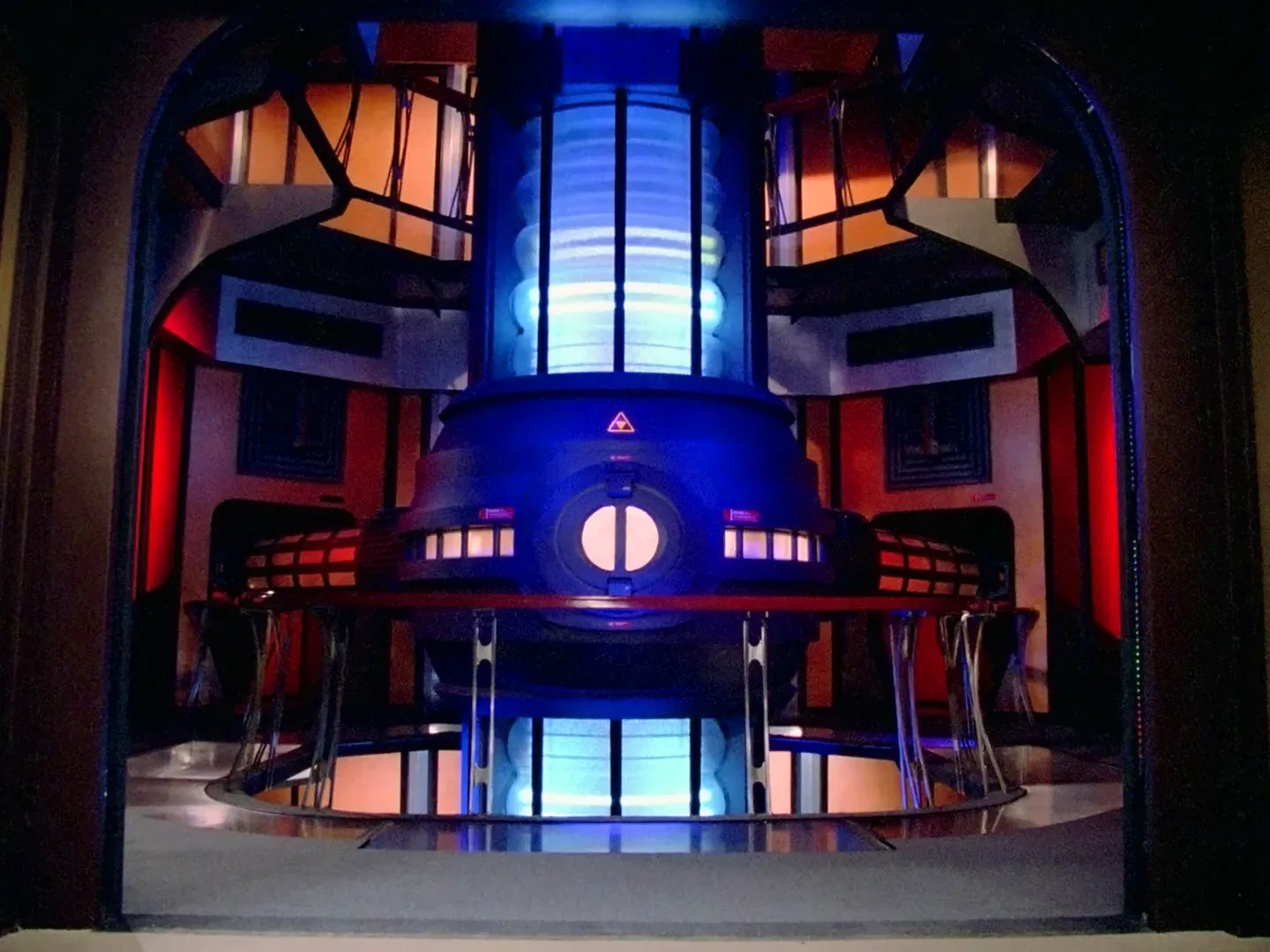
The columns light up... what if I made a lamp?
Materials
- 4x 12 inch plywood circles
- 6x 1&1/2" thick wooden dowels (at least 3 feet in length)
- 12x WS2812B LED strips (1m 30leds)
- 12x 12 inch wooden rings
- 12x jumbo white pool noodles
- 9x 5v2a power adapters
- Barrel connectors
- you only really need these if you are not using the custom pcb (see below), but they can be handy regardless for testing
- https://www.amazon.com/dp/B01J1WZENK?psc=1&ref=ppx_yo2ov_dt_b_product_details
- ESP32 board (I used the ESP32-C3-Devkit-M1)
- A bunch of small magnets
- Extension cords
- Wires, soldering equipment
- 3d printed parts
- First, the rings.
Take a look at the led strips. You will notice a connector with 3 pins (pwr, gnd, data), and 2 extra wires (white/red). Take 6 of the strips and solder longer wires onto the extra power wires. We will daisy chain the led strips to control them all together, and these extra power wires will help make sure power reaches all the leds evenly.
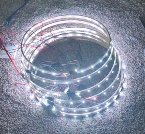
Remove the adhesive backing from the led strips and attach them to the wooden rings. You should now have 12 light up loops. You can connect them together to test them out, it should look like this:
To control the leds, you can really use any controller. While building I used a raspberry pi, but in the end I used an ESP32 microcontroller with WLED. I won't include steps for that here, it's very easy to find other guides online. The only settings I changed from default was the number of LEDs (I made each half of the lamp separately, so each half had 180 LEDs) and the max current (I found ~6A to be the brightest I could go reliably).
To power the rings, use the barrel jack connectors on each of the longer "powered" strips to plug in power supplies, and daisy chain them together, alternating the regular and long-wired strips. Connect the data pin of the first strip in the chain to your controller.
Once the rings are done, take your pool noodles and cut them in half lengthwise. Wrap each ring with a pool noodle. The white pool noodles act as diffusers for the leds, and give the rings their iconic warp core shape.
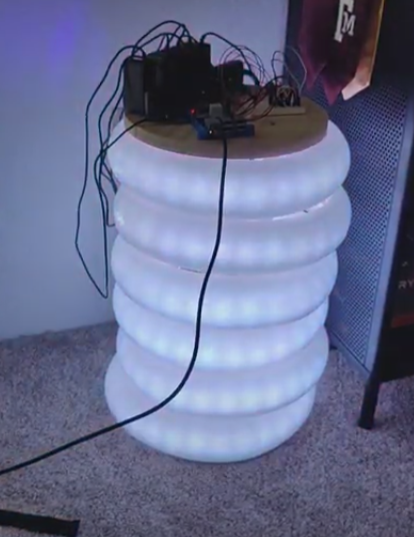
- Next, finish each half.
Stack 6 of your rings, alternating the regular and long-wired strips. Connect the daisy chain connectors for each strip, making sure you do it in the right direction.
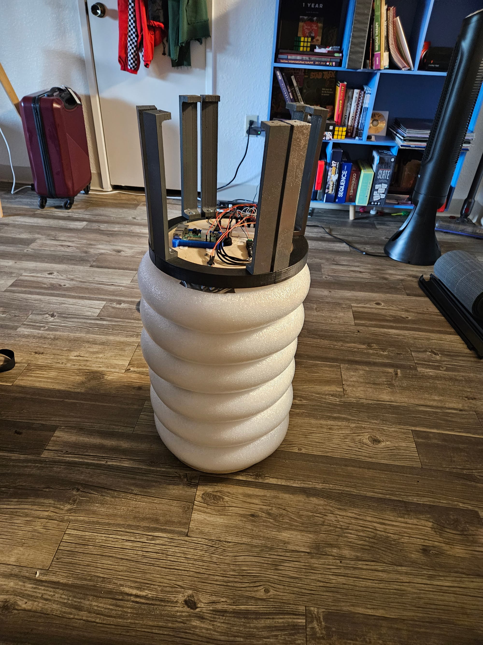
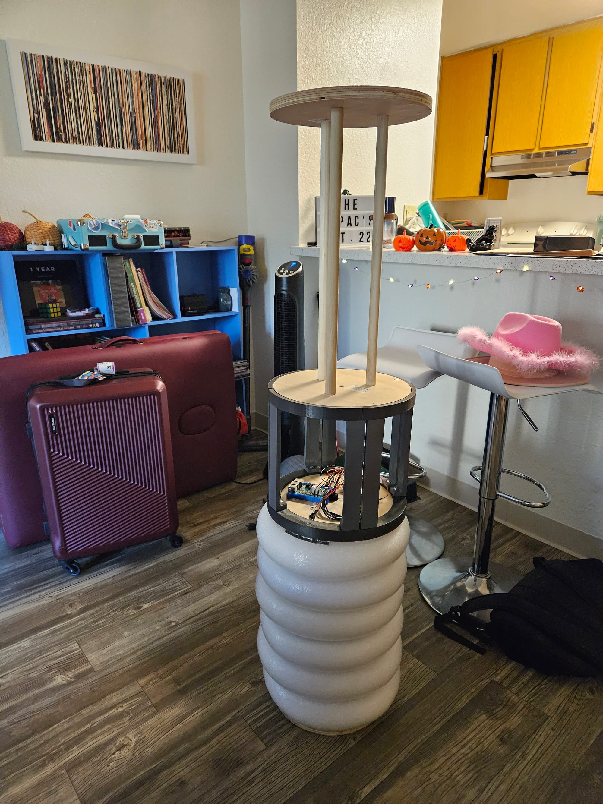
Cut the wooden dowels to the same height as the ring stack. Screw 3 of them into one of the wooden circles. This will form the skeleton of the lamp. Drill a large hole in the center of another of the wooden circles.
Take your stack of 6 rings, and slip them on the wooden skeleton. Use velcro straps to attach one of the extension cords to one of the dowels inside the lamp. You can connect all the power supplies for this half here. Screw the other wooden circle (the one with the hole) onto the other end to cap off the half. Pass the wires for the led strips through the hole.
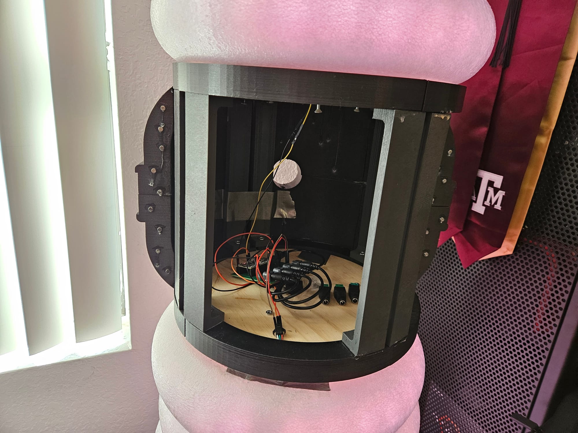
There are 2 options for connecting the electronics. You can use a breadboard, or a custom pcb. More info on the electronics (schematic, pcb) can be found below.
- Build out the center
The center is what will connect the two halves together. It consists of 2 parts: the skeleton and the shell. Both parts are 3d printed.
Download all the 3d models needed here: https://www.thingiverse.com/thing:6689793
Start by printing the skeleton pieces. Screw them in like so:
Next, print the shell pieces. Glue them together to form a front half and back half. Glue the back half onto the skeleton.
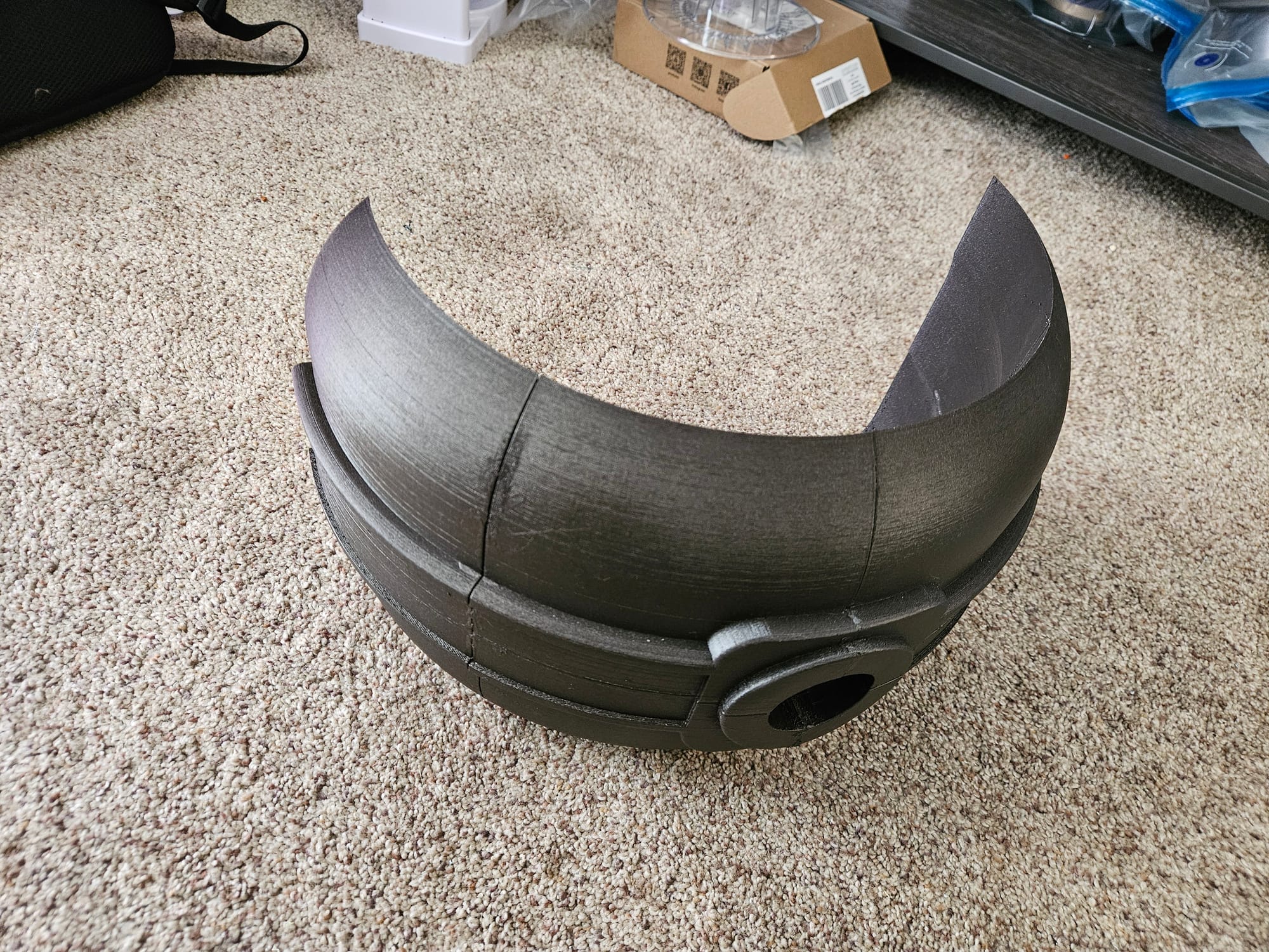
Glue a series of small magnets to the flat edge of each half of the shell. This will allow the front half of the shell to easily connect/disconnect for maintenance purposes.
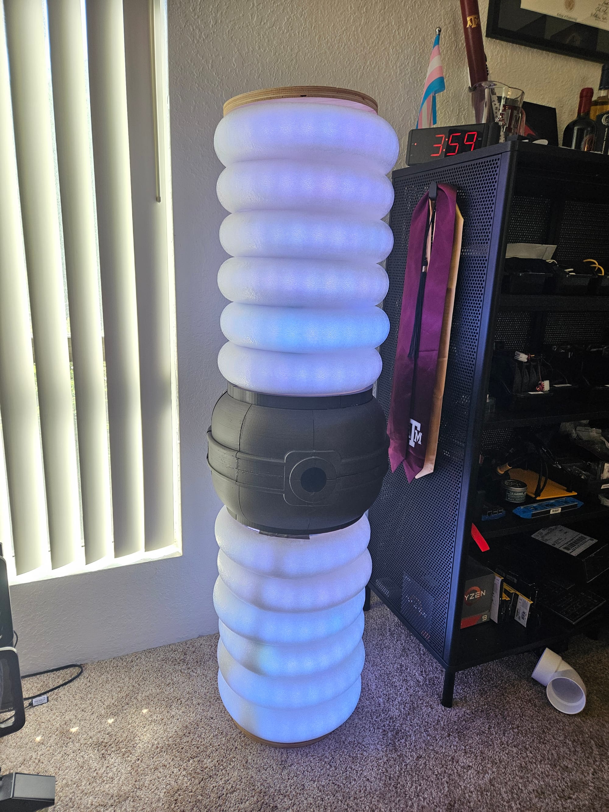
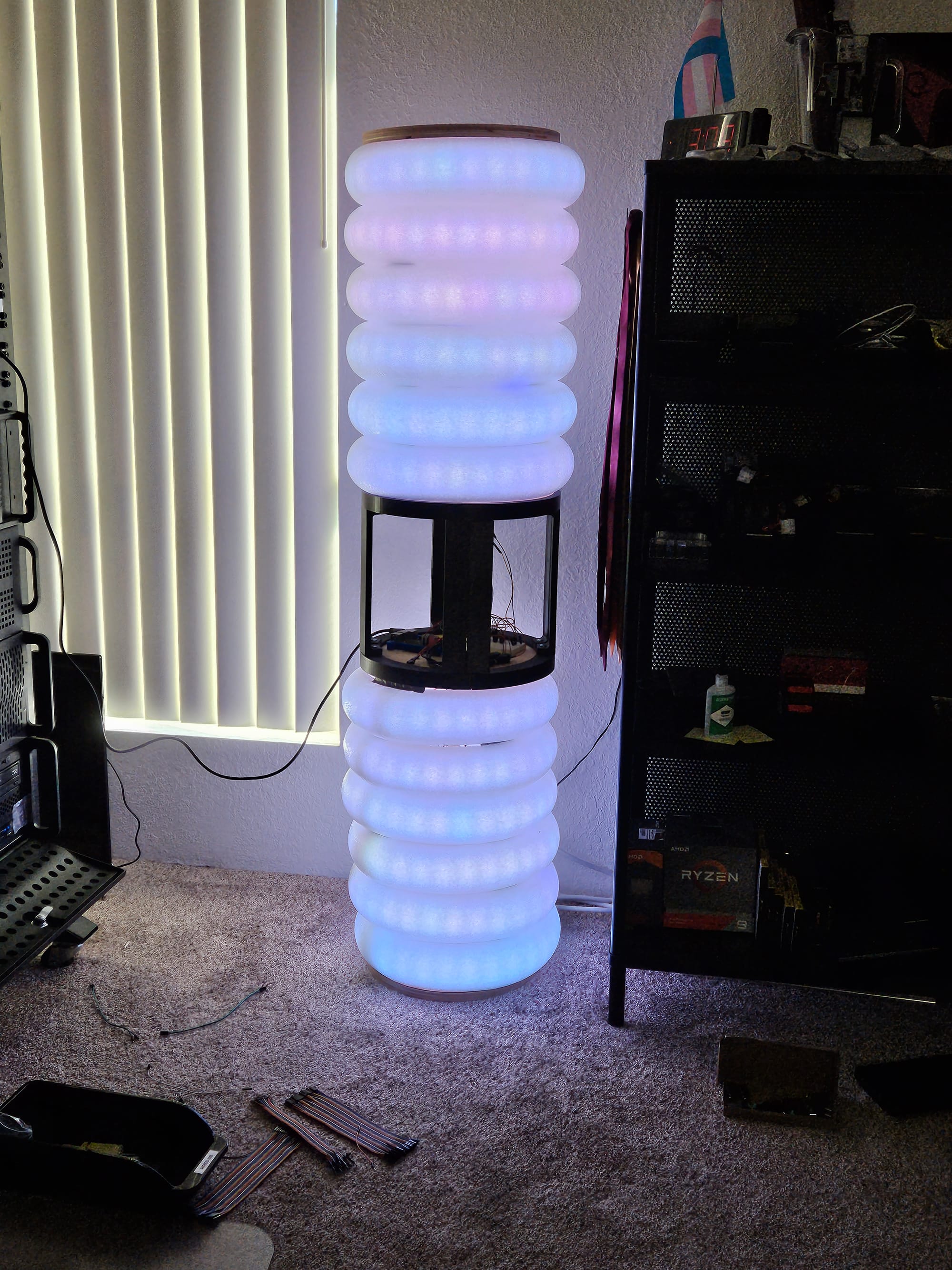
- All done! You now have a warp core lamp!
Electronics
Here is what I ended up with for the electronics. Feel free to assemble this however works best.
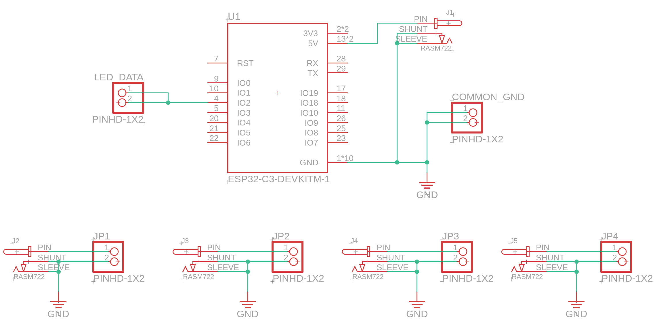
To summarize:
- Pin 2 of the ESP32 goes to the LED strips data pins
- Each "powered" led strip gets its own separate supply
- ALL ground pins are connected together
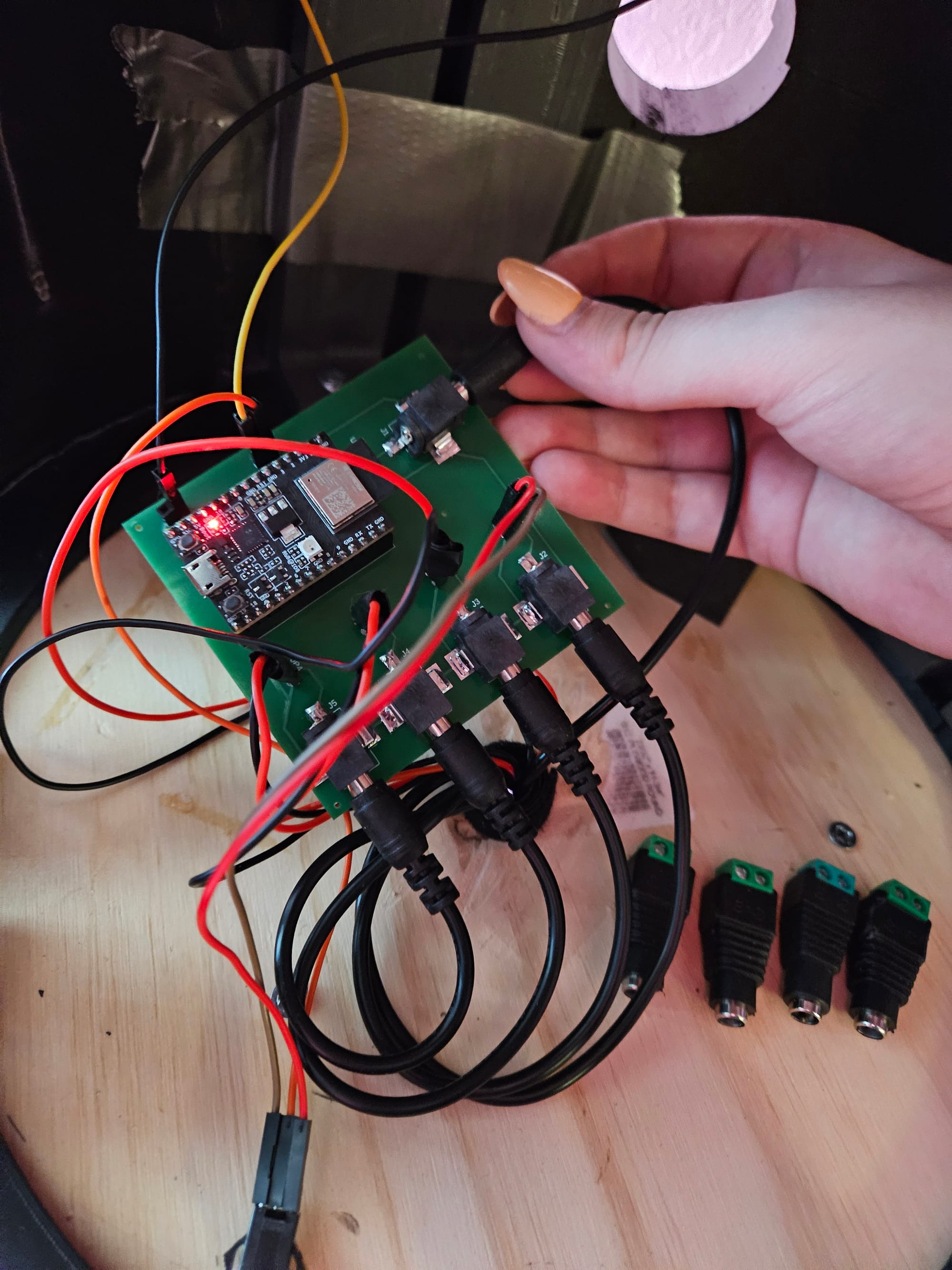
I used a custom pcb. I designed it in Fusion360 and manufactured with PCBWay. I ended up using 2 of them for the lamp. One board I assembled all 5 power connectors, and all the headers. The ESP32 went on this board. On the other board, I skipped the headers for the esp32 and only added 4 power connectors. I connected 1 of the LED_DATA pins and 1 of the COMMON_GND pins on both boards together to keep the two halves in sync.
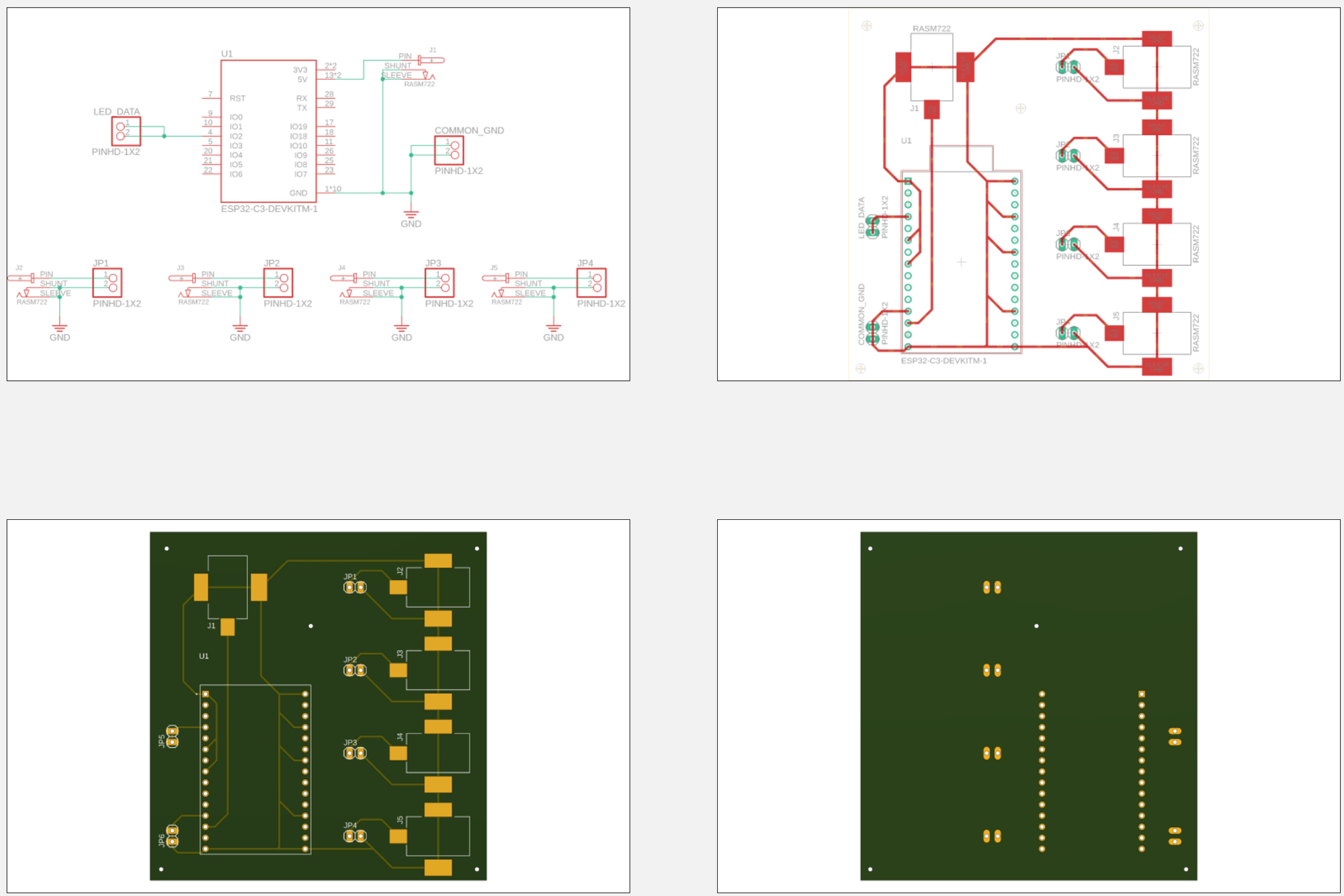
Components ordered from digikey:
- RASM722X power connectors (9)
- PPTC021LFBN-RC 2 pin headers (12)
- PPTC151LFBN-RC 15 pin headers (2)
Code
No code was used in the final product. If you are using an ESP32 microcontroller (highly recommend), just flash the WLED software on it.
Final Thoughts
Is it perfect? No. The center section doesn't light up, and rings aren't all identical, it does look a little skewed, and you can definitely see the individual LEDs.
To improve this, here are some ideas:
- Spend a bit more time on the 3d modeling for the center piece, maybe add some lights to it
- Make a sturdier skeleton that holds the rings in place better
- Get 60 LEDs/strip instead of 30
- Add something to the top/bottom to cover the wood
But at the end of the day, I'm pretty happy with how it turned out. If you end up making one, add a "make" on thingiverse to show it off! (https://www.thingiverse.com/thing:6689793/makes)